
Street Address
City, State, Zip
Phone Number
valve amplfiier specialist custom design of amps & studio gear
Your Custom Text Here
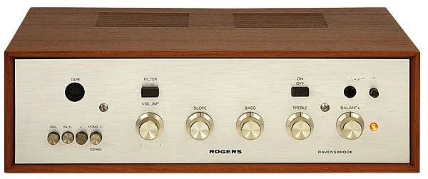
not the actual hifi
Rogers Ravensbrook
1) PCB restoration work
As printed circuit boards (PCBs) age they become prone to material erosion and dry joints due to the heat generated in areas where power resistors are located. Their excessive heat dissipation raises the temperature of their connecting leads, joints and the PCB traces (connections). This leads to the formation of dry joints but more importantly degrades the adhesion of these trace(s) to the PCB.
This amp has a number of such resistors which are continuously running hot (even when the amp idles) and the PCB sections where these resistors are located look slightly carbonized and weakened.
As a result a certain amount of reconstruction work was necessary to avoid further PCB deterioration; after removing the old solder a number of joints and their traces needed to be hardwired using special wire. This is a kind of stitching process that enhances mechanical stability before applying new solder.
Also, in order to improve the mechanical stability and durability of these connections, I replaced the old power resistors with new ones, same resistance value but larger and higher power rating types, for better heat dispersion of the joints. In places where the PCB and the traces are too thin, and/ or weakened so that they can no longer hold these new larger resistors properly, I fitted extra terminals mounted on insulated spacers and soldered these resistors onto the new terminals.
Many of the components inside the Ravensbrook amp get hot, regardless of whether you use the amp at loud volumes or not, even if the amp is just left on idling with no sound. The fact that the case is made out of wood (which is a heat insulator) exacerbates this problem and thus it is a good idea to switch off the amp when it is not being used.
2) Output stage design analysis and factors that must be considered when biasing and testing this amp.
The Ravensbrook III makes use of an old fashioned but advantageous (with respect to crossover distortion) biasing network. The two identical NPN power output transistors are driven by an audio phase splitter driver transformer and the overall (global) negative feedback (NFB) is lower than in most solid state power amps. Subjectively speaking, this feature contributes to its unique tone signature.
The biasing procedure in this amp is more complicated and lengthy: two biasing trimers are required instead of one (per channel). Also, the bias has to be checked repeatedly to ensure that it does not drift considerably in the positive direction to cause output transistor thermal runaway. Furthermore, the top biasing trimmer also affects output signal balance (marginally) which can then be corrected by an extra (third) dedicated balance trimmer, one per channel.
These trimmers physically deteriorate as they age and if they fail the amp could enter thermal runaway, reach over-dissipation and eventually fail in short-circuit mode. If the DC fuse (in the rear panel) is not blown in time this process can cause the power transformer to overheat and burn as well.
I therefore replaced all of these trimmers including the two balance ones.
There is also one NTC resistor (negative temperature coefficient thermistor) per each output transistor (two per channel) that reduces the standing (quiescent) current that flows through these transistors when the amp heats up at high volumes. Therefore the amps biasing current is higher when it is cold (i.e. at switch on) and then it gradually gets reduced to a lower value especially if the amp operates at high volumes.
The right channel will always conduct slightly less current especially during no signal periods, because one of its thermistors is located between the mains transformer (which continuously runs lukewarm after a while) and one of the output transistors which also gets warm.
3) I fitted RCA phono sockets for both the disc (phono) and radio (aux) inputs and banana sockets for the speaker outputs.
4) For safety I had to replace the mains switch with a rocker type which is now in the rear panel next to the mains lead entrance and I also rewired the earth bond.
5) I cleaned all potentiometers (especially the volume pot, see next paragraph) and switches with De-oxit; the volume and tone controls were very dirty and required to be cleaned twice.
6) Electrolytic Capacitors I have replaced:
a) All the large electrolytic caps in the power supply and DC voltage lines
b) The two large output electrolytics that couple the power output signal to the speaker
c) All of the electrolytics in the disc/phono stage, one or two were physically broken.
All of the new caps are modern good quality high temperature/ripple types.
I left the rest intact because they all tested good and in old equipment each time a component is replaced a certain amount of PCB work (as I explained) may be required due to the ageing PCB traces which often tend to come off the board.
Tests
I have tested the amp repeatedly during and after the biasing process for long periods of time and I am satisfied with its performance.
One minor issue (due to its design) is that if the output is not loaded the driver transformer in conjunction with the large output electrolytic capacitor introduces a minor low frequency instability at switch-on (thumping noise) which diminishes after a few seconds. However, If the output is loaded (i.e. a speaker is connected ) the noise disappears within a fraction of a second as in most output coupling capacitor power amps of that era.
In order to avoid this short lived instability the output must be connected to a load: either to the speakers or headphones which (headphones) are activated by pressing the 'headphone' switch on the front panel. This noise then quickly disappears (when the speakers or headphones are on) so often it is not noticeable.