
This is a restoration report on a Roost Session Master SM100R, can be considered broadly applicable to other high power vintage amps of that era.
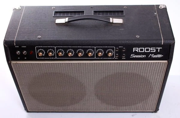
not the actual amp
( 1 ) Fault: tube failure that resulted in a blown high voltage (HT) fuse. The fuse was blown by a short surge of high current that did not last long enough to cause any serious discolouration (inside the fuse). This is a common occurrence in old tubes which gradually become 'gassy' and their internal components degrade with age: they electrically arc internally (often intermittently) and blow HT fuses.
Electrical leakage between electrodes and internal tube components can also take place in old tubes which often results in excessive current that causes overheating; a phenomenon that manifests itself as 'red-plating', a slow overload (unlike arcing) which does not always blow the fuse.
Arcing and leakage nearly always coexist, can happen simultaneously in ageing tubes and leakage and/or arcing in one power tube can affect the other power tubes too.
Electrically leaky/arching tubes can cause other components to fail and occasionally damage transformers if the fuse is not blown quickly enough.
This is because:
a ) An arcing power tube can cause the output transformer to arc too, and brake winding insulation(s)
b ) An electrically leaky or short-circuited tube due to arcing (or both) can result in excessive current flow through the windings of both mains and output transformers and burn the wire insulation (between windings) due to overheating.
The power tubes must be replaced with a matched and properly tested set and the biasing voltage must be adjusted, see ( 2) below.
( 2 ) The biasing circuit
The output stage must be biased at the right level of idle current (per tube) in order to optimize performance and ensure long tube lifespan.
Similar tube failures (that cause catastrophic knock on effects) as the ones mentioned in ( 1) can occur that if they (output tubes) are not biased correctly.
The adjustable biasing voltage in the existing circuit does not go high enough to accommodate all types of EL34 power tubes, a design flaw also found in some Hiwatt amps, and the reason was that they were fitting their amps with only one brand of EL34’s, direct from the tube manufacturer.
A simple mod can overcome this problem but I often build and install an improved version where each power tube can be biased separately.
This helps when there are minor idle current discrepancies between the power tubes. The amp can then be re-biased if mismatches occur after a year or so, considering that power tubes do not always age at an equal rate.
I always fit sampling current resistors so that the (idle) quiescent current on each power tube can be monitored.
( 3 )Tube sockets in decades old amps tend to become brittle and sooner or later electrically leaky so they must be replaced with new ceramic types.
( a ) The power tube sockets are operating hot and are carrying high voltages, up to nearly 500Vdc. In this amp (that operates on 450Vdc) these sockets are made out of bakelite (a plastic) and its insulating properties degrade with time. The high operating temperatures accelerate this degradation and so does condensation.
( b ) Condensation and moisture develops during gigs in venues but storing amps in humid spaces also leads to condensation issues inside the amp.
Visual inspection inside the chassis revealed small amounts of superficial rust in certain locations on the metal chassis. This in itself is not a problem but it is a telltale sign that the amp has been subjected to condensation (perhaps for some length of time) in its long past.
High temperatures, thermal cycling and condensation also degrade the mechanical rigidity of bakelite and other materials.
These are all common problems in amps of that age.
( 4 )
For similar age related safety and reliability issues:
( a ) High voltage terminals (like for example the turret board in the output stage) must be replaced because they become brittle and electrically leaky due to the degradation of their insulation between connections.
( b ) New power and stand-by switches and other mains and high voltage hardware (like the fuse holders) must be fitted.
( c )The AC mains line voltage select switch can be by-passed (to save cost) provided the amp is only used in the UK. This switch can be replaced with modern versions in the future if required.
( d ) A new IEC mains socket must be installed and the safety earth bond must be rewired according to modern UK standards. A new mains cable and plug must be fitted too.
( e )The output impedance select switch is very expensive (the new versions cost nearly £40) but it is still in good working order. After deep cleaning with de-oxit it must be checked after the soak tests for rigidity.
This switch is not in the high voltage section so its age is not a safety issue but it must provide a solid electrical connection to the output speaker output. Failing to do so can result in serious damage in the output tubes and even the output transformer.
At the moment this switch looks rigid enough and there are no signs of it failing any time soon.
( 5 ) The input and output sockets are inexpensive and must be replaced for future reliable operation.
( 6 ) Components like the power resistors in the output sockets and high voltage power supply lines must be replaced because they are far too old to ensure continuous reliable operation in the future.
( 7 ) The power and output transformers are in a good condition, clean and rust free. They are the most expensive and important components and the output transformer also shapes the amplifier's tone.
Both transformers are original vintage high quality Partridge types, same as the ones as the ones in the old Hiwatt amps.
( 8 ) All the electrolytic capacitors must be replaced with new high quality types, and the power stage capacitor pair must be high ripple 105 degree temperature types. These caps have developed a high ESR (equivalent series resistance) and their exterior shows signs of thermal degradation.
( 9 )The printed circuit board (PCB) and the preamp section
This section has been through several quick repairs in the past and it needs some straightening up.
( a ) The PCB itself must be removed, for rewiring/re-soldering work, some components may need replacing (particularly high wattage resistors) and weakened tracks must be repaired by hard wiring. This will eliminate existing (and avoid future) burnt out tracks due to mechanical stress and repeated heating and cooling.
( b ) The potentiometers behind the front panel control knobs are still intact but a couple of them are too old, their resistance has drifted and they need replacing. The rest are a bit scratchy but this can be easily fixed by thorough cleaning with de-oxit.
( c ) The small (12AX7/ECC83) preamp, phase inverter and reverb tubes test fine on the bench and they still work. However, they are low on emission and a couple of them are also noisy and slightly microphonic.
( 10 ) The reverb section
Everything works but the wiring has deteriorated over the years and consequently the reverb signal hums and breaks up intermittently.
The reverb tank which is inside the cabinet (under the speakers) is still intact but a couple of areas have become very rusty.
These connections must be rewired, a new reverb plug and socket must be installed and the whole reverb compartment, the tank itself and the cabinet need serious cleaning.
( 11 ) The speaker wiring is done very badly (the speaker wires are too thin and brittle) so it has to be replaced. If anything goes wrong there and the output of the amp accidentally disconnects itself from the speaker, serious damage will occur.